Controller Diagrams
This section contains diagrams for the main PX4 controllers.
The diagrams use the standard PX4 notation (and each have an annotated legend).
Multicopter Position Controller

- Estimates come from EKF2.
- This is a standard cascaded position-velocity loop.
- Depending on the mode, the outer (position) loop is bypassed (shown as a multiplexer after the outer loop). The position loop is only used when holding position or when the requested velocity in an axis is null.
- The integrator in the inner loop (velocity) controller includes an anti-reset windup (ARW) using a clamping method.
Fixed-Wing Attitude Controller
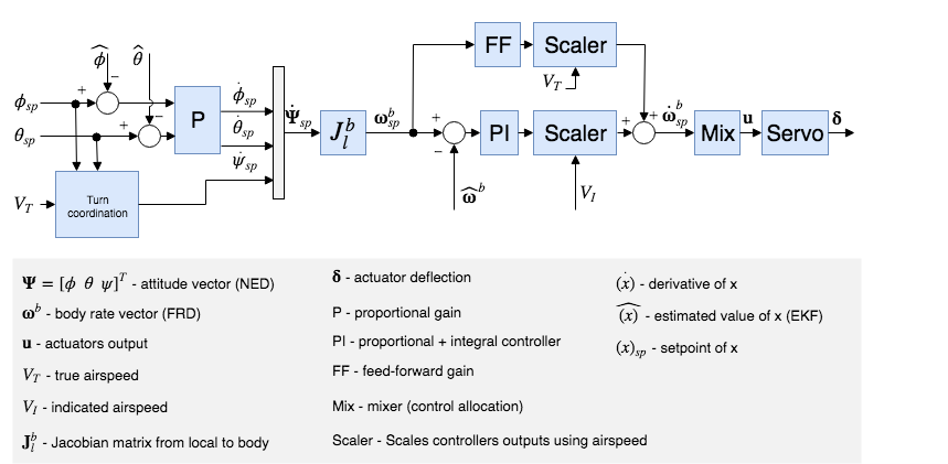
The attitude controller works using a cascaded loop method. The outer loop computes the error between the attitude setpoint and the estimated attitude that, multiplied by a gain (P controller), generates a rate setpoint. The inner loop then computes the error in rates and uses a PI (proportional + integral) controller to generate the desired angular acceleration.
The angular position of the control effectors (ailerons, elevators, rudders, ...) is then computed using this desired angular acceleration and a priori knowledge of the system through control allocation (also known as mixing). Furthermore, since the control surfaces are more effective at high speed and less effective at low speed, the controller - tuned for cruise speed - is scaled using the airspeed measurements (if such a sensor is used).
If no airspeed sensor is used then gain scheduling for the FW attitude controller is disabled (it's open loop); no correction is/can be made in TECS using airspeed feedback.
The feedforward gain is used to compensate for aerodynamic damping. Basically, the two main components of body-axis moments on an aircraft are produced by the control surfaces (ailerons, elevators, rudders, - producing the motion) and the aerodynamic damping (proportional to the body rates - counteracting the motion). In order to keep a constant rate, this damping can be compensated using feedforward in the rate loop.
The roll and pitch controllers have the same structure and the longitudinal and lateral dynamics are assumed to be uncoupled enough to work independently. The yaw controller, however, generates its yaw rate setpoint using the turn coordination constraint in order to minimize lateral acceleration, generated when the aircraft is slipping. The yaw rate controller also helps to counteract adverse yaw effects (https://youtu.be/sNV_SDDxuWk) and to damp the Dutch roll mode by providing extra directional damping.
Airspeed Scaling
The objective of this section is to explain with the help of equations why and how the output of the rate PI and feedforward (FF) controllers can be scaled with airspeed to improve the control performance. We will first present the simplified linear dimensional moment equation on the roll axis, then show the influence of airspeed on the direct moment generation and finally, the influence of airspeed during a constant roll.
As shown in the fixed-wing attitude controller above, the rate controllers produce angular acceleration setpoints for the control allocator (here named "mixer"). In order to generate these desired angular accelerations, the mixer produces torques using available aerodynamic control surfaces (e.g.: a standard airplane typically has two ailerons, two elevators and a rudder). The torques generated by those control surfaces is highly influenced by the relative airspeed and the air density, or more precisely, by the dynamic pressure. If no airspeed scaling is made, a controller tightly tuned for a certain cruise airspeed will make the aircraft oscillate at higher airspeed or will give bad tracking performance at low airspeed.
The reader should be aware of the difference between the true airspeed (TAS) and the indicated airspeed (IAS) as their values are significantly different when not flying at sea level.
The definition of the dynamic pressure is
,
where is the air density and the true airspeed (TAS).
Taking the roll axis for the rest of this section as an example, the dimensional roll moment can be written
,
where is the roll moment, the wing span and the reference surface.
The nondimensional roll moment derivative can be modeled using the aileron effectiveness derivative , the roll damping derivative and the dihedral derivative
,
where is the sideslip angle, the body roll rate and the aileron deflection.
Assuming a symmetric () and coordinated () aircraft, the equation can be simplified using only the rollrate damping and the roll moment produced by the ailerons
.
This final equation is then taken as a baseline for the two next subsections to determine the airspeed scaling expression required for the PI and the FF controllers.
Static torque (PI) scaling
At a zero rates condition (), the damping term vanishes and a constant - instantaneous - torque can be generated using
.
Extracting gives
,
where the first fraction is constant and the second one depends on the air density and the true airspeed squared.
Furthermore, instead of scaling with the air density and the TAS, it can be shown that the indicated airspeed (IAS, ) is inherently adjusted by the air density since at low altitude and speed, IAS can be converted to TAS using a simple density error factor
,
where is the air density as sea level, 15°C.
Squaring, rearranging and adding a 1/2 factor to both sides makes the dynamic pressure expression appear
.
We can now easily see that the dynamic pressure is proportional to the IAS squared
.
The scaler previously containing TAS and the air density can finally be written using IAS only
.
Rate (FF) scaling
The main use of the feedforward of the rate controller is to compensate for the natural rate damping. Starting again from the baseline dimensional equation but this time, during a roll at constant speed, the torque produced by the ailerons should exactly compensate for the damping such as
.
Rearranging to extract the ideal ailerons deflection gives
.
The first fraction gives the value of the ideal feedforward and we can see that the scaling is linear to the TAS. Note that the negative sign is then absorbed by the roll damping derivative which is also negative.
Conclusion
The output of the rate PI controller has to be scaled with the indicated airspeed (IAS) squared and the output of the rate feedforward (FF) has to be scaled with the true airspeed (TAS)
,
where and are the IAS and TAS at trim conditions.
Finally, since the actuator outputs are normalized and that the mixer and the servo blocks are assumed to be linear, we can rewrite this last equation as follows
,
and implement it directly in the rollrate, pitchrate and yawrate controllers.
Tuning recommendations
The beauty of this airspeed scaling algorithm is that it does not require any specific tuning. However, the quality of the airspeed measurements directly influences its performance.
Furthermore, to get the largest stable flight envelope, one should tune the attitude controllers at an airspeed value centered between the stall speed and the maximum airspeed of the vehicle (e.g.: an airplane that can fly between 15 and 25m/s should be tuned at 20m/s). This "tuning" airspeed should be set in the FW_AIRSPD_TRIM parameter.